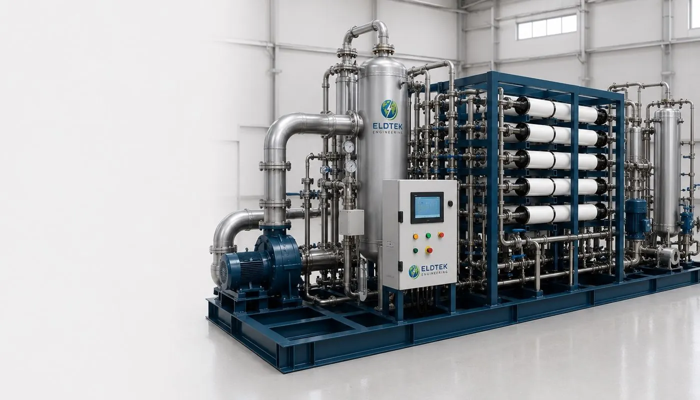
Membrane CO₂ capture: key features
| Feature | Eldtek membrane capture | What it means for you |
|---|---|---|
| Capture rate | Up to about 90% | The achievable rate depends on the CO₂ content of your flue gas, the number of membrane stages and the purity you need |
| Separation principle | Hollow-fibre polymer membranes that favour CO₂ | No chemical reaction and no solvent handling |
| Moving parts | None in the membrane modules | Membranes need very little maintenance. The system still needs a compressor, blower or vacuum pump to create the pressure difference |
| Solvents | None | No solvent make-up, no solvent waste and no regeneration cycle |
| Footprint | Compact and modular | Capacity grows by adding membrane modules |
| Retrofit | Retrofit-ready | Can be added to existing plants with minimal civil works |
| Output | Concentrated CO₂ stream | Ready for compression, utilisation or geological storage |
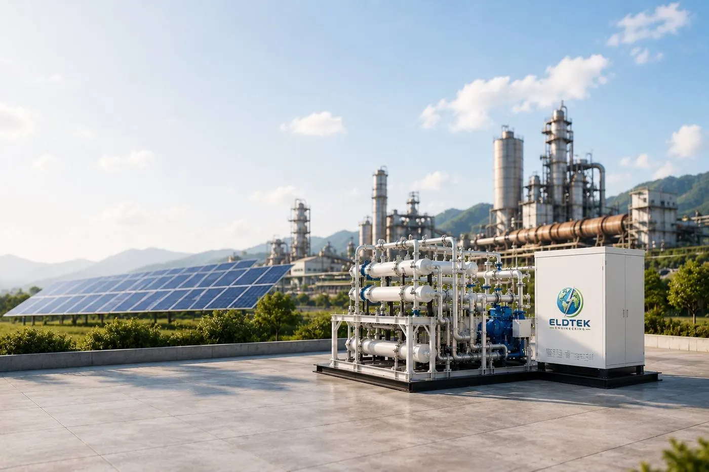
How membrane CO₂ capture works
Selective permeation
A membrane is a thin polymer layer that some gases cross faster than others. CO₂ dissolves into the polymer and diffuses through it faster than nitrogen, the main component of flue gas. The gas that crosses the membrane (the permeate) is rich in CO₂. The gas that stays on the feed side (the retentate) is mostly nitrogen.
The pressure difference
Separation needs a driving force. Flue gas is near atmospheric pressure, so the system compresses the feed, pulls a vacuum on the permeate side, or does both. The compressor or vacuum pump is therefore the main energy user.
Membrane stages
One membrane stage rarely gives both high recovery and high purity. Designs use two or more stages, where the permeate of one stage feeds the next, and sometimes recycle part of the gas. Extra stages raise purity but add equipment, so the layout is set for each site.
Membrane capture or amine scrubbing: how to choose
Amine scrubbing is the most established way to capture CO₂ from flue gas. This comparison helps you judge which route suits your stream.
| Factor | Membrane capture | Amine scrubbing |
|---|---|---|
| Chemicals | None | Amine solvent, with make-up and waste handling |
| Heat or steam | Not needed for the separation | Large heat demand to regenerate the solvent |
| Main energy use | Electricity for compression or vacuum | Steam or heat, plus pumps |
| Footprint | Compact and modular | Tall absorber and stripper columns |
| Best suited to | Richer CO₂ streams and moderate purity or recovery targets | Dilute streams and very high purity or very high recovery |
| Scaling | Add membrane modules | Larger columns, scaled by design |
Send us your flue gas data and Eldtek's engineers will tell you whether membranes fit.
Where membrane capture is used
Eldtek's systems target industrial point sources, including cement kilns, steel furnaces, power plants, chemical facilities and waste-to-energy plants. CO₂ content differs widely between these sources and strongly affects membrane performance.
- Gas-turbine exhaust: about 3–4% CO₂
- Coal-fired boilers: about 12–14% CO₂
- Cement kilns: about 14–33% CO₂
These are indicative values from published literature, and your own gas analysis decides the design. Richer streams are generally easier for membranes. Dilute streams usually need more stages or a step that raises the CO₂ concentration first.
From flue gas to captured CO₂: the process chain
- Conditioning. Dust is removed and the gas is cooled and treated so that particles, acid gases and excess water do not damage the membranes.
- Pressure difference. A blower, compressor or vacuum pump creates the driving force across the membrane.
- Membrane stages. One or more stages separate CO₂ from nitrogen and the other flue gas components.
- Drying and compression. The CO₂ stream is dried and compressed to the pressure needed for transport or use.
- Use or storage. The CO₂ is utilised, for example in chemicals, fuels, food-grade CO₂ or greenhouses, or sent for geological storage.
Capture rate, purity and energy: the trade-off
Three numbers pull against each other. The capture rate is the share of the CO₂ in the flue gas that is removed. Purity is how concentrated the CO₂ product is. Energy is the electricity used for each tonne captured.
Pushing capture rate and purity higher usually means more stages, more membrane area and more compression, which increases energy use and cost. Eldtek's figure of up to about 90% capture describes the top of the range. A design aimed at a lower capture rate can use less energy per tonne, so the right target is a project decision.
What we need to size your CO₂ capture system
- Flue gas flow in Nm³/h, wet or dry.
- CO₂ concentration as a percentage by volume.
- Temperature and pressure at the capture point.
- Other components, such as dust, sulphur oxides, nitrogen oxides, oxygen and water vapour.
- Your target capture rate and the CO₂ purity you need.
- What happens to the CO₂ next, such as utilisation or storage, and the delivery pressure.
- Site constraints, including space, power and available utilities.
Capture systems often sit beside other Eldtek plants. See the battery energy storage systems and hydrogen generation plants pages for related equipment.
Frequently asked questions
What is a CO₂ capture system?
Membrane CO₂ capture passes flue gas across polymer membranes that let CO₂ through faster than nitrogen. The CO₂-rich permeate is collected and the CO₂-depleted gas is released.
What capture rate can Eldtek's system reach?
Eldtek states that up to about 90% is achievable. The actual rate depends on the CO₂ content of the flue gas, the number of membrane stages and the purity you need.
Does membrane capture use solvents or steam?
No. Membrane capture needs no solvent and no steam for regeneration. Its main energy input is electricity for a compressor, blower or vacuum pump.
Which industries can use it?
Cement kilns, steel furnaces, power plants, chemical facilities and waste-to-energy plants.
Can a membrane system be added to an existing plant?
Yes. Eldtek states that its compact, modular systems can be retrofitted with minimal civil works.
What happens to the captured CO₂?
It is dried and compressed, then used (for example in chemicals, fuels or greenhouses) or sent for geological storage.
What flue gas data do I need to provide?
Gas flow in Nm³/h, CO₂ percentage, temperature, pressure, other components such as dust, sulphur oxides, nitrogen oxides and water vapour, and your capture and purity targets.
How do I request a quotation?
Send your gas data and targets through the contact form or by email to projects@eldtek.com. Eldtek aims to respond within 24 hours.